In precision automation and CNC machinery design, the square flanged linear bearing represents a critical component for ensuring stable, rigid, and predictable straight-line movement. Among the standard variations, the LMEK20UU-a European standard square flanged linear motion bearing with a 20mm bore-is highly favored for its integrated flange structure, which simplifies mounting and eliminates the need for specialized external housings.
However, design engineers and maintenance technicians frequently ask: How do you adjust the internal parameters, such as preload and radial clearance, of an LMEK20UU bearing? Unlike split-type housings or adjustable pillow blocks, a standard flanged linear bearing features a rigid, one-piece hardened steel outer cylinder. This means its internal parameters cannot be adjusted via external screws, shims, or mounting bolts. Instead, adjusting the fitment parameters of an LMEK20UU requires precision control over mating shaft tolerances, exact housing alignment, and tailored factory specifications.

Technical Architecture of the LMEK20UU
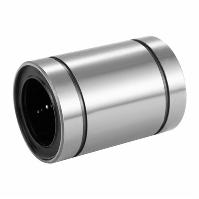
Understanding why standard flanged bearings possess fixed internal geometries requires an examination of their structural blueprint. The LMEK20UU consists of a hardened high-carbon chromium bearing steel (GCr15) outer cylinder integrated seamlessly with a square mounting flange on one end. It features an inner inscribed circle diameter of 20mm, an outer cylinder diameter of 32mm, a total length of 45mm, and a square flange measuring 42mm by 42mm.
Inside the outer cylinder, a synthetic resin ball retainer directs multiple closed loops of precision-ground steel balls. These balls continuously recirculate through load-bearing pathways and non-load return zones. Because the outer steel cylinder is entirely solid and unslotted, its internal diameter is locked at the factory.
Therefore, any attempt to squeeze or alter the outer shell through mounting force will only warp the raceway and destroy the component. True adjustments must be executed through peripheral engineering choices.
The Correct Engineering Method to Adjust Radial Clearance and Preload
To achieve either a tight, high-precision preload (zero-clearance) or a loose, low-friction fit, engineers must manipulate the external mating components rather than the bearing itself.
1. Shaft Tolerance Selection: The Ultimate Adjustment Variable
The radial clearance of an LMEK20UU is entirely dictated by the dimensional difference between the bearing's internal inscribed ball diameter and the outside diameter of the mating linear shaft. By specifying different precision shaft tolerances, you effectively "adjust" the final operational parameters:
- For High Precision and Rigidity (Negative Clearance / Light Preload): Pair the LMEK20UU with a shaft ground to a g6 or h6 tolerance. This minimizes radial play, ensuring maximum guiding accuracy and eliminating vibrational backlash in high-end CNC routing axes.
- For High-Speed or Low-Friction Applications (Positive Clearance): Select a shaft machined to an f6 tolerance. The slightly smaller shaft diameter increases the internal radial clearance, providing a loose fit that easily accommodates microscopic thermal expansion and high linear velocities.
2. Utilizing Factory Customizations
If a specific internal clearance range cannot be achieved via shaft selection alone, procurement managers must request factory-level customization during the ordering stage. Manufacturers can sort internal steel balls into micro-inch size classifications. Packing the outer cylinder with slightly larger precision balls establishes an internal preload directly from the assembly line, while smaller balls expand the internal clearance zone.
Correct Alignment and Housing Fitment Parameters
While internal tolerances depend on the shaft, the external orientation and running smoothness depend entirely on perpendicularity and mounting alignment. Misalignment creates localized stress clusters that mimic an excessive, catastrophic preload condition.
Perpendicularity of the Mounting Wall
Because the square flange of the LMEK20UU bolts directly against a flat structural bulkhead, the mounting surface must be completely perpendicular to the path of travel. If the structural plate is warped or unmachined, tightening the four flange bolts will tilt the bearing cylinder relative to the shaft. This tilt pinches the circulating steel balls at the entry and exit points, causing severe binding, rapid retainer wear, and loud operational noise.
Concentricity Across Dual-Shaft Systems
Most linear motion stages utilize two parallel shafts running in tandem. If the distance between the two shafts varies even by a few micrometers along the stroke length, the rigid square flanges of the bearings will prevent self-alignment. The system will experience mechanical binding as it enters narrower zones. Guaranteeing exact parallelism using precise laser alignment tools or high-end CNC-milled baseplates is the only way to ensure uniform resistance.
Specialized Product Variations for Divergent Applications
Depending on structural design parameters and environmental conditions, different flanged and specialized configurations may be selected to optimize system performance:
- LMF Series Alternative: If the machine frame requires a round footprint rather than a square mounting boundary, the LMF20UU offers identical internal technical metrics but utilizes a circular flange. This variation is ideal for space-constrained cylindrical bores.
- LMH Series for Space Optimization: In applications experiencing strict vertical or horizontal height limitations, the LMH20UU features a cut-flange design where two parallel sides are machined flat. This allows multiple bearings to be nested closely together.
- Advanced Plating Enhancements: For machinery operating in humid packaging zones or medical cleanrooms, specifying an LMH20UU Nickel Plating or stainless steel finish adds a hard layer of protection, preventing surface corrosion from disrupting the smooth recirculation of the rolling elements.
Lubrication Management as a Performance Parameter
Lubrication thickness acts as a physical parameter that alters the dampening, friction coefficient, and thermal thresholds of the LMEK20UU system.
Grease Lubrication for High Load and Dampening
For standard industrial speeds and heavy load cycles, filling the internal ball cavities with high-quality lithium-soap-based grease is highly recommended. The grease forms a viscous cushion around each steel ball, absorbing micro-vibrations and providing exceptional long-term wear protection. Grease should be replenished via external maintenance schedules to flush out any ingress of ambient dust particles.
Oil Lubrication for Ultra-Low Resistance
In high-speed automation systems where a low friction coefficient is paramount, light machine oil should be continuously applied to the surface of the light linear guide shaft. Oil shears much faster than grease, allowing the internal steel balls to recirculate with minimal resistance, which reduces operational heat generation and prevents thermal expansion from seizing the internal tracking clearances.
Manufacturing Excellence and Structural Integrity: The SQ Framework
Sourcing linear motion components that exhibit flawless dimensional consistency across large batches is essential for automated machinery lines.
Zhejiang Siqiang Bearing Manufacturing Co., Ltd. (SQ) is a premier high-tech enterprise founded in 2007 and serves as the Vice President unit of the Lishui Rolling Functional Components Association. Operating from a state-of-the-art 19,800-square-meter modern production workshop equipped with more than 100 industry-leading CNC units, automated grinding machines, and precision testing apparatuses, SQ maintains strict compliance with the ISO9001 quality management system.
Our rigorous testing protocols eliminate dimensional deviations, ensuring that every LMEK20UU, ball screw, and hardened shaft matches global metric standards perfectly. We offer international B2B clients completely bespoke customization services, including custom brand logos, customized packaging solutions, and advanced anti-corrosion surface coatings tailored to your precise industrial requirements.

Operational Testing and Validation Protocol
- Once you have established your chosen shaft tolerances and bolted the square flange into position, validate the system using a standardized engineering testing protocol:
- Manual Drag Test: Disconnect the electric drive motors and slide the linear stage manually along the entire length of the stroke. The resistance must feel uniform; any sudden increase in resistance points to parallel shaft misalignment rather than an internal bearing defect.
- Thermal Profiling: Run the machinery at operational speeds for 30 minutes and monitor the outer cylinder temperature using an infrared thermometer. A stable thermal plateau indicates optimal clearance, whereas continuous temperature spikes indicate a tight fit or insufficient lubrication.
- Acoustic Inspection: Listen closely to the recirculating zones. A smooth, low-pitched whirring signifies correct ball circulation, while sharp clicking sounds indicate a pinched outer cylinder caused by poor mounting wall perpendicularity.
Conclusion: Achieving Optimum Accuracy Through Precision Engineering
In conclusion, because the LMEK20UU features a rigid, high-carbon steel outer shell, you cannot adjust its internal parameters using shims or mounting hardware. True optimization is achieved by selecting precision-ground shafts with calculated tolerances (such as g6, h6, or f6) to control internal radial clearance and preload.
By pairing accurate shaft selection with flawless perpendicular mounting surfaces, hydrophobic lubricants, and world-class components manufactured by SQ, industrial operators can ensure maximum operational life, smooth travel dynamics, and exceptional positioning accuracy across heavy industrial machinery and high-speed automation platforms.
Need Technical Blueprinting or Bulk Procurement Pricing? Contact SQ's Technical Consulting Engineers today to receive official CAD drawings, shaft compatibility charts, and factory-direct volume quotes for your automated machinery lines.
Step - by - Step Adjustment Process
- Initial Inspection: Before you start adjusting, give the bearing a thorough inspection. Check for any signs of damage, such as cracks or excessive wear. Make sure the mounting surface is clean and flat.
- Preload Adjustment: Use the shims to adjust the preload. Start with a small amount of preload and gradually increase it while monitoring the bearing's performance. You can use a torque wrench to ensure that the mounting bolts are tightened evenly.
- Clearance Measurement: Use the feeler gauge to measure the clearance. If the clearance is outside the recommended range, make the necessary adjustments. Remember, a small adjustment can make a big difference.
- Lubrication: Apply the appropriate lubricant according to the operating conditions. If you're using a lubrication system, make sure it's working properly.
- Test Run: After making all the adjustments, run the system for a short period. Listen for any unusual noises or vibrations. Check the temperature of the bearing to make sure it's not overheating.
Related Products
If you're interested in other similar products, we also offer LMH20UU Nickel Plating, LMF20UU Stainless Steel, and LMH20UU. These products have their own unique features and can be used in different applications.
Conclusion
Adjusting the parameters of LMEK20UU is not as complicated as it may seem. With the right tools and a little bit of knowledge, you can ensure that your bearing performs at its best. If you have any questions or need more detailed information, don't hesitate to reach out to us. We're here to help you with your purchasing and technical needs. Whether you're a small business or a large industrial enterprise, we can provide you with the best solutions for your linear bearing requirements. So, if you're looking to buy LMEK20UU or any of our other products, just get in touch, and let's start a great business relationship!
References
- Linear Bearing Handbook, published by Bearing Manufacturers Association
- Industrial Machinery Maintenance Guide, by Mechanical Engineering Press